Gozzard 36A (pre 1990)
Compression Post Kit – Installation Guidelines
As our fleet ages we are finally seeing some issues with the construction of the earlier boats… the good news is we are still here to help and we recognize the value of helping our owners to correct these and any other problems that may crop up in the future. It is good for all of us as it maintains the vessels value and in the process our reputation.
At some point in our production run of the G36 (and maybe some of you can help us with this because our records do not indicate exactly what hull # this change occurred but we believe it is somewhere around 1990 possible with the G36B) we upgraded our compression post to a larger diameter round stainless steel tube… eventually this was replaced again with an integral vacuum infused composite post bonded to a composite main bulkhead after 1999 through current. The earlier G36s all had a mild steel compression post. Now before you all go off on us for using steel in a marine environment… let me take this opportunity to remind you that back in the day we were still building our reputation. We wanted to build the best boats we could but we still had to sell them and market acceptance eventually allowed us to put the price up and invest more in our boats. We still do this today – every new Gozzard is better than the boat before (although it is getting harder these days as you start to approach the pinnacle of quality). In any case know that mild steel is actually stronger than SS and we felt the bilge was heavily raked enough that this area of the boat would remain dry. Obviously it did to a point… some boat better than others but here we are. Eventually even the best maintained G36 will suffer from corrosion and to aid with this issue we have developed a kit that allows for the replacement of the bottom of the post.
The following are the general instructions for installation. Read these through and understand how all this goes before you attempt the install. Pay particular attention to the last paragraphs to see if the boat needs more preloading (adjustment) to begin with before actually cutting the post. Depending on how bad the compression post is, there may be settling of the deck that can be corrected with this install.
First – it is best if the mast is removed if at all possible. All of the installs we have done here at the factory have been done without the mast loads on the compression post. If you attempt to do it with the mast in place you must absolutely relax all the rigging so that there is no load on deck except the weight of the spar.
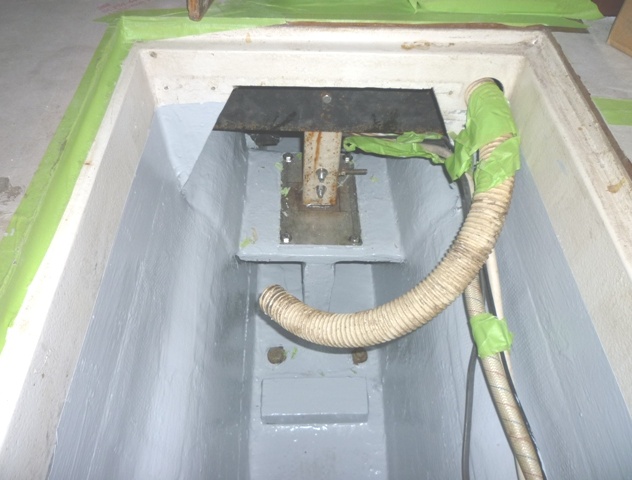
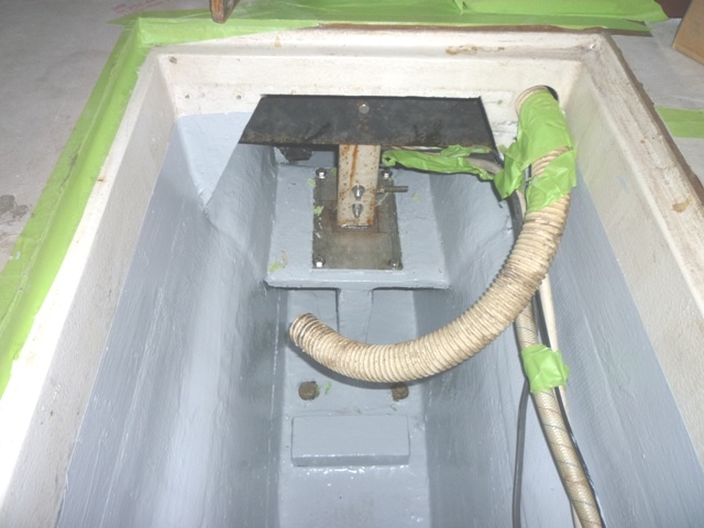
You will need to gain access to the area by removing any equipment forward and aft of the mast post… this would include bilge pumps and high water alarms in the forward bilge and the tank in the aft bilge. Once removed the next step is to determine where to make the cut on the old compression post. You are going to cut the post and remove the bottom section that is corroded, then slide a “T” shaped support with a new base plate in from astern. As you slide this in it will preload the remaining post… lifting the deck (and mast) back to its original location. Then the “T” support is glassed in place and then bolted up.
First I will describe how this is done and then describe the limiting factors that may alter the location of the cut. If there are no other limiting factors, the cut can be located by simply sliding the “T” support up to the post from the aft side with the stainless base sitting on top… then mark the post level with the top of the SS base plate. You would then make a square cut in the compression tube at this mark. We find a 4” grinder with a cut off wheel is the best tool for this… although caution must be made to contain all the metal particles created by the cut – these will rust so they must be collected and cleaned up. Remember you are saving the tube above the cut and removing/scrapping the tube below the cut including the old base. Make the cut as square as possible and it is recommended you mark the cut with a small hand square so you can follow the cut. You will have an opportunity to clean it up further once the bottom section of the tube is removed.
Factors that might affect the location of the cut include how far up the corrosion has extended (this would be the minimum length) and if there is a wiring exit that limits how far up you can go (this would be the maximum length). Realize you have to glass the “T” support on both sides of the vertical leg (under) so you do not want to make the “T” too low as it makes it difficult to work. We find the “T” support as supplied generally works without adjustment. That said if it needs adjusting then simply cut a determine measurement off the bottom while maintaining the angle of the bottom cut. You will note it is tapered, shorter at the front to match the slope of the keel sump while maintaining a level base for the compression post plate. This allows the “T” support to get higher as it is pushed in further towards the bow exactly like a wedge. Other factors include excessive deck compression or settling which is usually best seen by how the privacy panel and forward cabin door close within their frames or openings… this was all nice and square with even gaps when the boat was originally manufactured. Often how much preload can be determined by watching these gaps close (adjust) when preloading the “T” support in place.
Obviously is it best to cut the post long at first and then adjust shorter. If the post is cut too long then the “T” support will not be able to be hammered in far enough under the base plate to fully support the new SS base plate. It would be too tight to allow it so slide completely under. In this case you can hammer the ”T” support back out and shorten the post until the support is completely under the base… once it is under it is good enough… the support is made longer fore and aft than required to allow for this type of adjust and you do not have to have it perfectly centered under the SS base plate. As long as the new base plate is completely supported under it is good enough.
So once cut you remove the bottom of the old compression post and discard – note there are two bolts up through the plate from the bottom through keep sump. Simply cut these off with the grinder flush with the old base. You may have to pry the old base over these stubs to remove. If clearance is a problem simply make another cut in the lower (soon to be discarded) section of the tube. Once the old post is removed, prep the area for laminating. You need to grind off all the original bilge paint to 95 % raw glass… this must be keep clean of grease and oil contamination from this point until the glass is laminated.
Now offer the SS base plate over the tube and then slide the “T” support in from the back as a dry run. It should just start before things start to bind up… then proceed to hammer the wedge (created by the “T” support) in toward the bow. You should find that as the “T” slides up the slope created by the keel sump, it gets tighter and will preload the compression post. Stop when you have the appropriate preload (things stop moving). What we are after is to have the post preloaded and have the base completely supported by the “T”. If it needs to be adjusted, hammer it back out and adjust. Again it is not necessary to have the SS base centered on the “T” in the fore and aft direction – only completely supported. Use the sliding privacy panel on the bulkhead opening to gauge how much things have settled – all the corners were square when it was first made. It usually takes a couple of dry runs before we have the final position. Once that is established we need to tab glass the support in place perminetly.
Glassing the support – if there are any gaps between the flat of the “T” and the side of the keel sump, fill these with a resin and glass mix. The support needs to be glass on both sides of the vertical leg and on both sides of the keel sump on the flat of the “T” with 6 layers of 1810 E Glass (supplied). Extend onto the hull at least 4” and it helps to taper each layer a little further onto the hull. Do not glass on to the SS base plate… just up to it. Once the glass has set up then bolt the SS base plate down to prevent movement.
The kit includes a FRP “T”, a stainless steel base plate with welded receiver socket for the square post and 4 bolts and the glass material (1810 XM E glass). Shipping is extra and the resin is not included. Call for pricing.